

Clear purpose and what you’ll gain
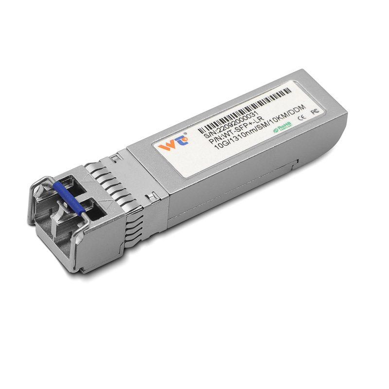
This user-centered guide helps network engineers and operations staff install a 100G QSFP28 LR4 transceiver on a single-mode backbone with care and speed. It focuses on tasks, not theory, so you can move from parts inventory to verified link quickly. For teams who still mix 10G optics into aggregation layers, the 10g sfp+ transceiver and the 10g transceiver examples here show how smaller ports and higher-density QSFP28 lanes coexist in real racks. This advice aligns with common single-mode deployments (ITU-T G.652 single-mode fiber) and keeps the focus on practical checks: polarity, connector type, and power budget.
Preparation: parts, labeling, and safety checks
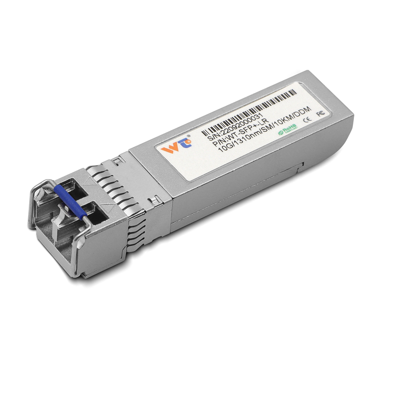
Gather QSFP28 LR4 modules, pre-terminated LC duplex patch cords or MPO trunk where needed, and a clean work surface. Verify module part numbers and firmware compatibility against your switch vendor’s list. Label both ends of every fiber run before you touch connectors. Confirm you have a low-power mode plan for hot-swap if the switch supports it. Keep isopropyl wipes and a fiber inspection scope ready—cleanliness matters more than luck.
Ten practical installation steps
Follow these concise steps in order; each step removes common rework later.
1. Power down the port or set link to administrative down when possible.
2. Inspect the LC or MPO connector with a scope; clean until no debris remains.
3. Verify single-mode fiber type and matching end-face polish—no mixing of MM/SM.
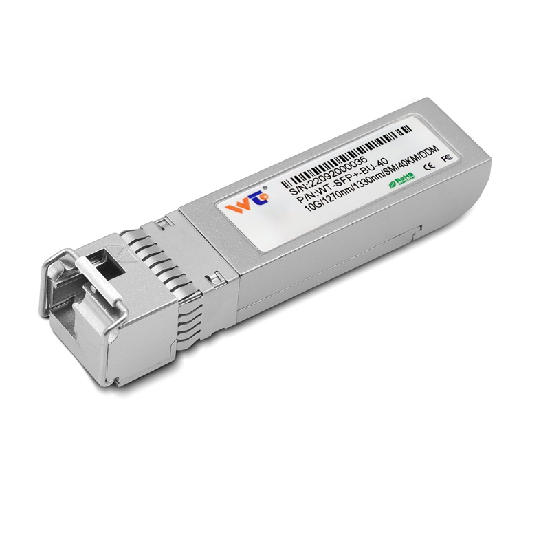
4. Insert QSFP28 LR4 gently; ensure the latch clicks and module seats flush.
5. Connect LC duplex or MPO trunk using labeled ends; confirm polarity.
6. Enable the port and watch for stable CD/remote fault lights.
7. Use switch diagnostics (DOM) to check module temperature and transmit power.
8. Run an optical power check and compare to the calculated link budget.
9. Run a short throughput test (traffic generator or jumbo frame test) and observe error counters.
10. Document the serial, firmware, and measured power in your change record.
Common mistakes and quick remedies
Avoid these recurring problems: wrong connector type, dirty end faces, and mismatched fiber type. If you see remote faults after insertion, recheck polarity and fiber type first. If transmit power is low but DOM shows a healthy laser, clean again—micro-debris can mimic module failure. Keep spare certified patch cords and a replacement 10g transceiver in the kit to swap for isolation testing—this usually narrows the fault to cable or module.
Validation: essential tests after installation
Run three straightforward checks: optical power vs. link budget, interface counters for CRC/errored frames, and a short throughput run. OTDR traces are helpful for long trunks, but for most backbone handoffs a power meter and BER check give faster, actionable results. Record DOM values—Tx/Rx power and temperature—so you have a baseline for future troubleshooting.
User tips for long-term reliability
Keep connectors capped when not in use and maintain a rolling cleaning schedule for high-density panels. Track firmware revisions for QSFP28 modules and update only after validation in a lab segment. Standardize on LC duplex or MPO termination across the rack to reduce human error—consistent hardware reduces incidents.
Three golden rules for selection and measurement
1. Match optics to fiber and link budget: choose LR4 for single-mode distances and verify expected loss plus margin. 2. Prioritize measurable diagnostics: DOM and power meters beat guesswork. 3. Standardize spares and labeling: parts parity and clear IDs cut mean time to repair. These rules let teams predict outcomes and measure improvements after each change. For practical sourcing and dependable parts, WINTOP supports consistent inventory and tested modules across deployments—WINTOP. —