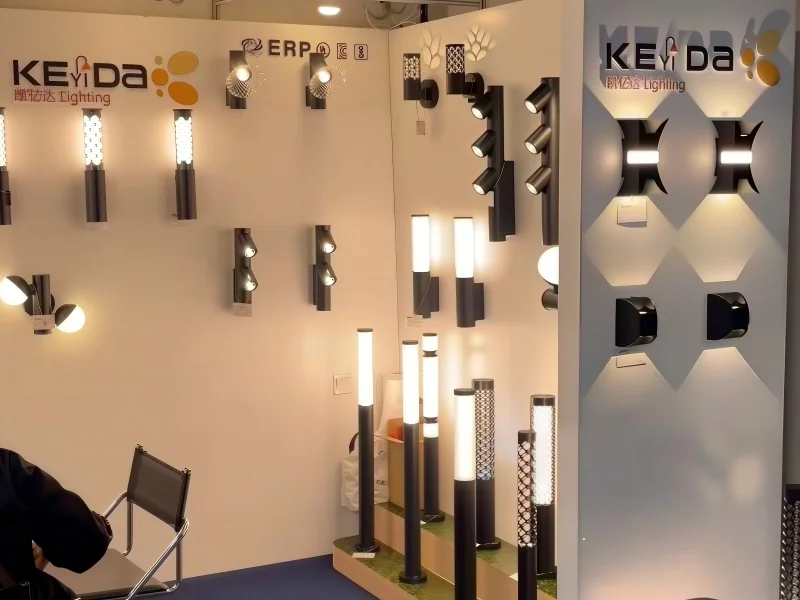


Framework overview: why treat bollards as structural inspiration
Integrating high‑efficiency bollard lights into a building façade requires more than aesthetic alignment; it needs a repeatable framework that ties electrical performance, anchoring details, and maintenance access to the architectural intent. This piece lays out a practical sequence you can apply during design development, specification, and handover. Early coordination with an exterior lighting company makes the process measurable and avoids late-stage rework driven by mismatched lumen output or IP rating assumptions.
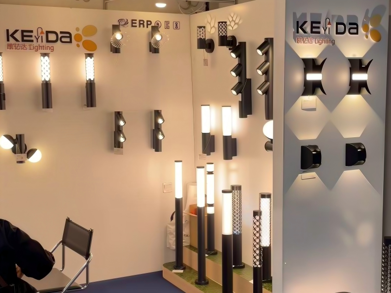
Step 1 — Establish performance and code anchors
Begin by defining measurable targets: target lumen output, correlated colour temperature (CCT), expected lifetime (LM‑80), and minimum IP rating for the intended exposure. Referencing standards such as IES LM‑79 and LM‑80 helps translate manufacturer data into real performance expectations. A useful rule of thumb: specify the photometric distribution and a cut‑off angle early so lighting and façade teams agree on spill control and visual comfort.
Step 2 — Map structural and mechanical interfaces
Treat bollards as modular structural elements that demand clear façade anchoring details. Coordinate anchor bolt locations, sleeve depths, and load transfer to the substructure. Ensure the façade team understands required clearances for LED driver access and conduit runs. Consider corrosion‑resistant finishes and gasket details where cladding meets the bollard base to prevent water ingress and galvanic issues.

Step 3 — Electrical integration and service strategy
Plan for accessible service points: put drivers and fuses in weatherproof enclosures or locate them within serviceable plinths. Specify low‑voltage vs mains supply early to define transformer or driver placement. Address surge protection, dimming protocol (e.g., DALI or 0–10V), and emergency power if pathway lighting supports egress. When you align these electrical choices with façade penetrations, you reduce the risk of disruptive late‑stage changes.
Step 4 — Photometrics and visual coordination
Use photometric simulations to align bollard placements with façade texture and sightlines. Lumen spacing and mounting height should reflect both functional requirements and the façade’s vertical rhythm. If the design uses mixed luminaires — for instance, wall‑mounted up/down lights with bollards — balance CCT and glare control so the façade reads as a single system rather than a patchwork.
Step 5 — Procurement, testing and QA
Specify acceptance tests tied to manufacturer data: LM‑79 report verification, on‑site lumen checks, and IP ingress testing where feasible. Require sample units to be installed in-situ for a trial period if the project tolerates it. Evaluate vendors not only by unit cost but by documented QA rates and historical lead‑time adherence — those tell you how reliably an exterior lighting company or an outdoor wall lamp manufacturer will perform at scale.
Design trade-offs and practical examples
There are common trade‑offs you should anticipate. Higher lumen efficacy reduces energy and heat but might require larger heat sinks and affect form factor. Tighter cut‑off angles control glare yet change perceived brightness on textured façades. In Vancouver, many waterfront upgrade projects demonstrated that switching to LED bollards cut operational energy by a wide margin — often reported between 50–75% compared with legacy halogen systems — while improving durability under marine conditions. These outcomes are typical when projects adhere to a clear framework rather than ad hoc decisions.
Common mistakes and how the framework prevents them
Teams often assume that a selected bollard will “just fit” on a parapet or planter — without confirming structural capacity or conduit routing. Another recurring error is neglecting driver access until after cladding is installed, which forces rework. The framework forces early verification of physical interfaces and serviceability so that installation is predictable and maintainable — and it keeps warranties valid by ensuring manufacturer installation requirements are met.
Implementation checklist
Use this short checklist at design freeze:
- Document lumen, CCT, IP rating, and LM‑79/LM‑80 evidence.
- Confirm anchor and sleeve details with structural engineer.
- Map driver, dimming protocol, and surge protection locations.
- Run photometric simulations with façade textures applied.
- Specify in‑situ sample trials and acceptance criteria.
These items reduce ambiguity during procurement and tighten the handover to operations — which is where long‑term value is realised.
Advisory: three golden rules for successful integration
1) Prioritise measurable specs over descriptive adjectives — require LM‑79 reports, IP ratings, and clear photometrics. 2) Design for serviceability — ensure driver and fuse access without removing major cladding or hardscape. 3) Insist on sample trials under real site conditions before committing to final production and installation.
When applied consistently, this framework converts a set of fixtures into a cohesive façade system that performs for years. Keyida understands how those technical choices translate into durable outcomes for clients — and that practical alignment is often the difference between an elegant façade and one that demands costly fixes. —