

Why this problem matters now
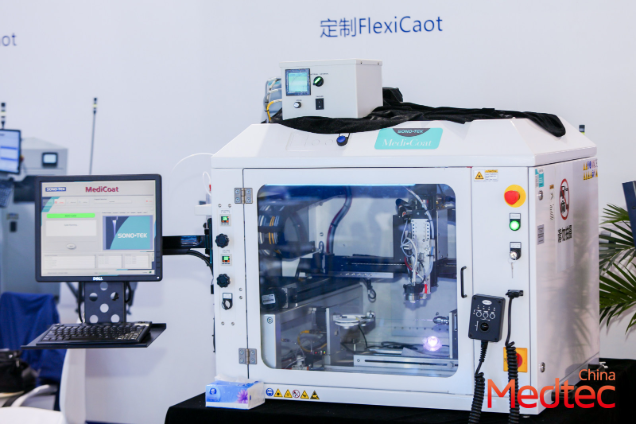
Signal integrity failures and dimensional drift in liquid silicone rubber (LSR) overmolded subassemblies are sneaky. They show up after a few thermal cycles or during sterilization, and suddenly your connector traces misbehave. I’ve seen the conversation shift on the floor and at shows — including notes from Medtec China in Shanghai — so this write-up takes a practical, problem-driven tack for teams dealing with LSR molding and PCB overmolds in China medical device manufacturing. The goal: identify the root problems and give clear fixes that you can validate on the line.
Root causes that actually break things
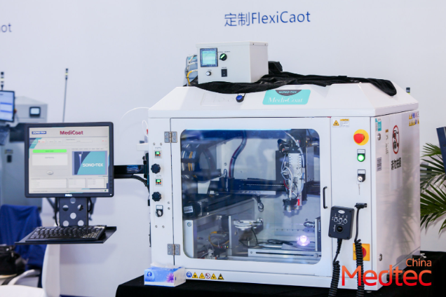
Three failure modes dominate: material movement (cure shrinkage and thermal mismatch), poor interface control (incomplete wetting of pads or seams), and electromagnetic interference (EMI) changes once the elastomer settles. LSR molding introduces compressive forces during cure; tooling tolerances amplify micro-shifts. Add aggressive sterilization cycles and you get creeping dimensional change. Those shifts translate into impedance jumps and intermittent contact — classic signal integrity headaches. Keep the language concrete: cure shrinkage, mold venting, and adhesion chemistry matter.
Practical diagnostics that don’t waste a week
Start simple and build evidence. Inspect cross-sections and measure critical stack-ups with a coordinate-measuring probe. Use time-lapse of functional tests across temperature baths and log impedance traces for a 48–72 hour window. If impedance drifts outside your baseline by more than 3–5%, flag it. Thermal cycling plus humidity exposure will reveal unstable interfaces faster than a production burn-in. Take photos and dimension logs at three stages: post-mold, post-cure, and post-sterilization — then correlate those to electrical test vectors. A short lab run often exposes the pattern—don’t overcomplicate it.
Shop-floor fixes that actually stick
Adjust the molding cycle and tooling before you rewrite the whole assembly. Improve venting and trimming to reduce trapped gas and skin effects. Move to modified LSR grades for lower cure shrinkage when signal traces sit close to the surface. For inserts, use mechanical locking features or micro-textured anchoring to control peel. Post-cure profiles can stabilize elastomer dimensions; a controlled post-cure at a modest elevated temperature will lock the geometry faster. Also tighten your process control on shot size and mold temperature — small swings change contact pressure and impedance. And yes, pay attention to EMI shields: an overmold that shifts can alter coupling and force a redesign of shield placement — get the baseline before you iterate.

What teams commonly get wrong
They over-index on material specs and under-investigate the tooling. Designers demand a low-shrink LSR but keep an open runner design that allows part movement — the mismatch sabotages reliability. Others skip retention sampling after sterilization cycles and assume “it’ll be fine.” That’s not fine. Keep a discipline: dimension control plans, electrical baselines, and retention samples through expected sterilization regimes. Also avoid last-minute supplier swaps without a micro-audit; elastomer batch variability does matter.
Three golden rules: metrics to choose with
1) Impedance stability: design for an impedance variation margin ≤5% across expected thermal and humidity ranges. That gives you headroom for minor material drift without signal failures. 2) Dimensional drift limit: specify a maximum cumulative drift (for critical clearances) of ≤50 μm after production cycle and sterilization. That keeps mating geometry predictable. 3) Production yield threshold: require a functional yield ≥98% on a representative pilot run before design sign-off. If your yield is lower, iterate tooling and cure profiles until you hit the threshold. These metrics let you select materials, tooling, and test protocols with measurable end goals.
Closing take
Address the root—tooling and cure—before reworking the whole PCB stack; measure impedance and dimensional drift, set clear thresholds, and hold suppliers to them. Field observations at Medtec China and Shanghai production audits show teams that pair modest tooling changes with a thoughtful post-cure stabilize faster and deliver fewer returns. Practical steps, clear metrics, and disciplined sampling win the day—Medtec. A tight fix, simple checks, better uptime.